
This tradition lasted through the early PDP-8 and PDP-11 models, although the PDP-11 CPU light displays were modest compared to earlier CPUs. The earliest PDP-11 disk controllers were very much a match for the earlier machines, though, and included indicator panels which displayed a great deal of information.
Alas, the cost of such displays was high, and they were dropped from later controllers. Their passing was mourned by those who had had the opportunity to work with them, though; in addition to helping with debugging (both hardware and software issues), and giving an extensive insight into how the machine was operating, they were also just a lot of fun. Today, 'das blinkenlitz' (as the are often referred to now) are a focus of the computer heritage movement.
This page documents many of the DEC indicator panels, so that when one is seen, it can be determined what kind of indicator panel it was (the 'inlay' which had the captions for the meaning of the individual lights on it usually did not say what kind of device it was for).
The PDP-8 and PDP-11, although not 36-bit machines, also used the same indicator panel, but in general did not include any 36-bit fields. (The exception is the RP11-C, which was able to read packs written on a PDP-10, and thus included a 36-bit shift register, which was displayed on the RP11-C panel.) The 18-bit PDP-15 also used (extensively!) this indicator panel.
Limited engineering drawings (they do not include the full mechanical drawings) for this indicator panel are included in the RF11 Engineering Drawings set; the indicator panel is shown on pp. 186-190. Of particular interest are the parts lists, which include all the inlays extant as of the date of the drawings (10/1972).
According to those prints, the list of available inlays at that point (other than the ones illustrated below) included:
The tables below list the indicator panels available for each machine type, and include links to larger images of the panel (where we have images - anyone who has an image of one of the missing panel is urged to provide it), and (for some), detailed information about the panels.
| Image | Device | Details | Comments |
|---|---|---|---|
|
RF08 | ||
| RK08 | Like the TC08, only two rows of lights, out of the four available, were used. | ||
|
TC08 |
| Image | Device | Details | Comments |
|---|---|---|---|
| Image coming | BA10 | Hardcopy Control; it contained information on a number of different devices: line printer, card punch, plotter | |
| Image coming | DA10 | Computer Interace; used to connect to a variety of 12- and 18-bit DEC computers | |
| Image coming | DC10 | Data Line Scanner | |
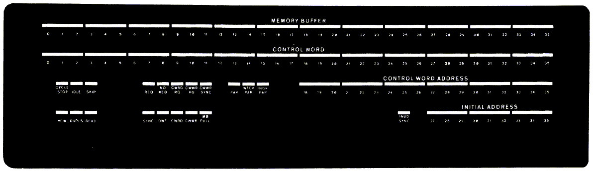 |
DF10 | Data Channel; DMA channel used with tapes and disks | |
| Image coming | DS10 | Synchronous Line | |
| Image coming | MB10 | Core Memory | |
| Image coming | MD10 | Core Memory | |
| Image coming | RC10 | Fixed-head disk | |
| Image coming | RM10B | Drum | |
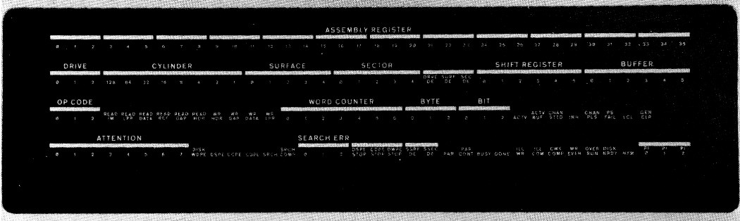 |
RP10 | Disk | |
| Image coming | TD10 | DECtape | |
| Image coming | TM10 | Magape |
| Image | Device | Details | Comments |
|---|---|---|---|
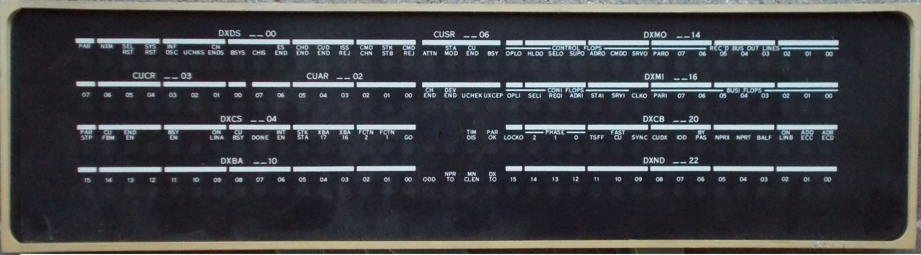 |
DX11 | The DX11 is an IBM 360/370 Channel interface. | |
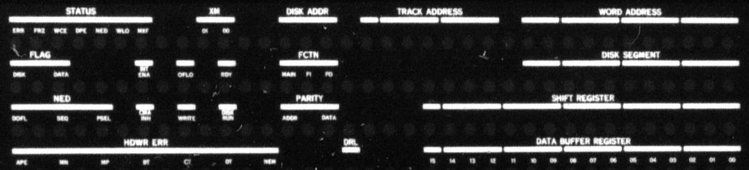 |
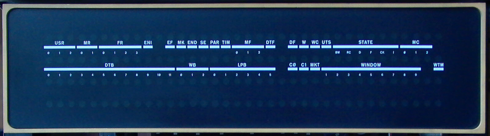
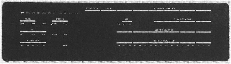
RF11 | RF11 details | Easily recognized in low-resolution images with the two groups of three
single lights on the left-hand side.
For those who are finding the captions hard to read in this image, a drawing is available here. |
 |
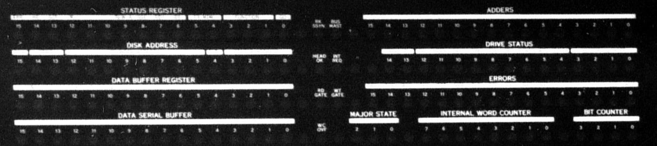
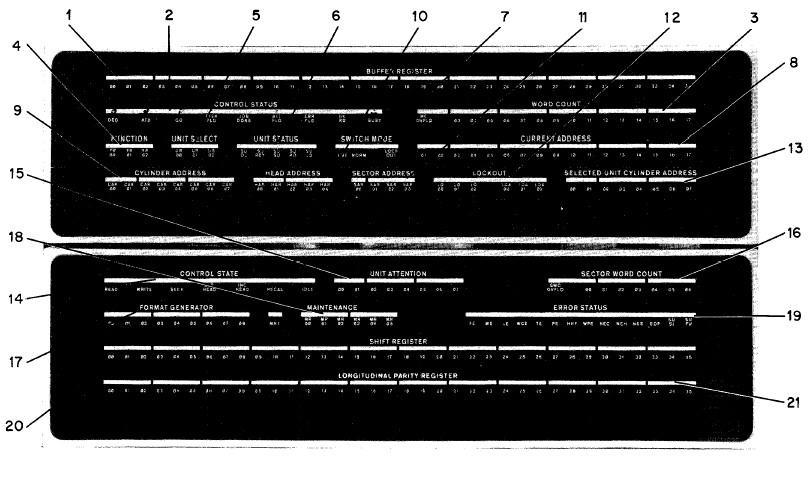
RP11 | RP11 details | Two variants are known for this, known as "RP11" and "RP11-C" in the DEC documentation; they differ only in that one contains two lights (ORDY and IRDY, on the right hand of the second row down) which are not in the other. |
 |
RK11-'B' | Images of this panel appear in DEC promotional literature for the PDP-11, but as far as is known DEC never shipping this panel as a product. Extensive coverage of what appears to be a pre-production (hence the notional 'B' naming) version of the RK11 which used this panel is available here. | |
| RK11-C | RK11-C details | The RK11-C engineering drawings show that it was wired to connect up to
an indicator panel, but as far as is known, none were ever actually produced.
None of the extant RK11-C documentation mentions such a panel, and the
indicator panel engineering drawings do not list an RK11-C inlay.
Using the engineering drawings, and the known pinout of the indicator panel, it is possible to determine what such an RK11-C panel would look like; a mockup can be seen here. (Although note that the individual light captions are somewhat hypothetical, since no such inlay was ever produced - although the signals that drive them, and hence their meaning, is known.) |
| Image | Device | Details | Comments |
|---|---|---|---|
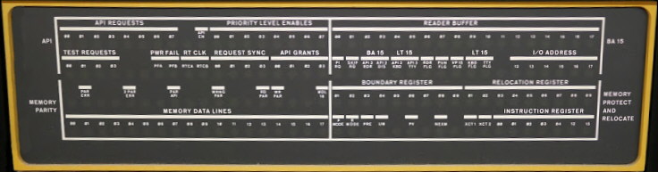 |
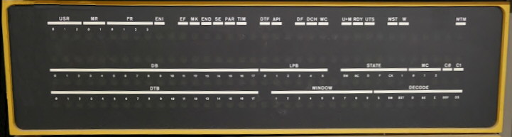
This panel does not go with a specific device, but includes information from a number of CPU-related systems; the lower rigft quadrant is mostly the KT15 memory management, the upper left is the KA15 priority interrupt system, but there is general CPU/system information throughout (memory parity, power fail, instruction register); the top right line seems to be the paper tape reader input buffer. | ||
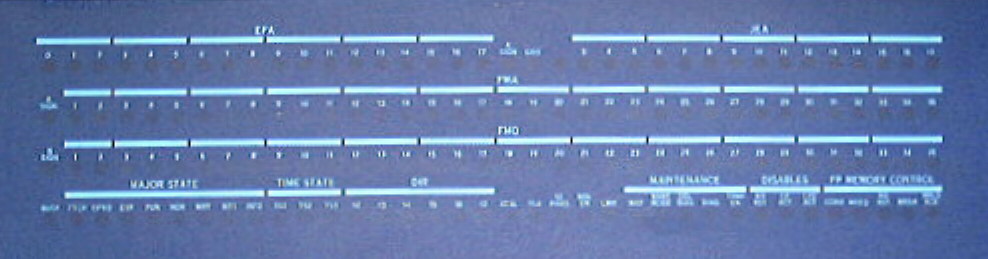 |
FP15 | As the drawing of the indicator panel connector (pg. 73 of the prints) shows, this panel is full. | |
 |
VT15 | ||
 |
RF15 | Identical to the RF09 indicator panel. | |
 |
RP15 | The RP15 had two indicator panels. | |
 |
TC15 |
The inlay itself is 4-23/32" high, and 18-9/16" wide. (All measurements are given in imperial units, since that's what they would have been specified in at the time the originals were made - and they come out exact, below, if given in those units.) The corners - shown here in another scan - are 3/8" radius (as measured with a corner gauge).
The distance from the top of the holes in the top row to the bottom of those in the bottom row is 2-7/8"; from the left of the left-most hole to the right of the right-most is 15-9/16". So, the inter-row distance (hole center to center) is 2-5/8 / 3 = 7/8" (exactly); the inter-column distance (again, center-center) is 15-5/16 / 35 = 7/16" (again, exactly).
Individual holes are each 1/4" wide. That makes the distance from the left edge of one hole, to the right edge of the next, 3/16"; and similarly, from the bottom of one, to the top of the next, is 5/8".
From the left of the left-most hole, to the left edge of the inlay is 1-1/2"; from the top of the top-most hole, to the top edge of the inlay is 15/16"; and from the bottom of the bottom-most hole to the bottom edge of the inlay is 7/8". (It is not clear if that 1/16" difference is important or not.)
See Also:
Back to JNC's home page
© Copyright 2015-2017, 2021, 2023 by J. Noel Chiappa
Last updated: 9/March/2023